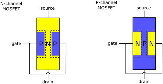

Here, D represents the Drain terminal, S represents the source, and G represents the gate terminal. The structure of NPN JFET is shown below: N-channel refers to the JFET with center channel doped with the N-type or Pentavalent impurities and the two side slabs doped with the P-type or trivalent impurities. The working of both the JFET are similar expect the majority carriers. JFET is further categorized as n-channel JFET and p-channel JFET. It is intended to increase the drain current in the transistor. It is also known as the controlling voltage of JFET. It is the voltage across the terminals G and S, i.e., gate and source. Its relation with drain describes the attraction of charge from the D to constitute the current. The connection of V DS is such that its relation with the source describes the movement of charge carriers away from the S towards D. It is the voltage across the terminals D and S, i.e., drain and source. Let's discuss the connection of these two voltage sources across the three terminals of the JFET. There are two voltage sources V DS and V GS. It is defined as the region between the two gate terminals that possess the movement of majority carriers from the source to the drain. The part of the transistor where the n-type doping is present in large amounts is known as the channel. The current generated through this terminal is known as gate current (I G). It is applied in the direction to make the p-n junction reverse biased. The voltage between the gate and source is known as V GS. The same procedure creates the impurities doped on the two regions as the p-n junctions. In the case of n-channel, two p-regions are present on the two sides of the transistor, named as the gate. Gate consists of the heavily doped region present on both sides of the transistor. The voltage between the drain and source is known as V DS. The direction of current in JFET is determined in the opposite direction to the flow of electrons and in the same direction to the flow of holes.

The voltage is connected across the drain and source. The current generated due to the majority charge carriers through this terminal is the drain current (I D). The majority carriers' electrons (in the case of n-channel) and holes (in the case of p-channel) exit from the transistor through the drain terminal. DrainĪ drain terminal is present at the top of the transistor. The current generated due to the majority charge carriers through this terminal is known as source current (I S). The majority carriers' electrons (in the case of n-channel) and holes (in the p-channel) enter through the source into the transistor.

The source is the terminal at the bottom of the transistor, as shown above. The three terminals of JFET are as follows: Source The structure and symbol of JFET are shown below: Terminals of JFET The Junction Field Effect Transistor has three terminals, drain, source, and gate. Let's discuss the concept, structure, types with working, and characteristics of JFET in detail. FET is also known as JFET (Junction Field Effect Transistor). FET or Field Effect Transistor is also a type of transistor-like Bipolar Junction Transistor.


 0 kommentar(er)
